Radinium Fire
Documentation
- Radinium Fire Hardware Setup
- QuickStart Guide
- Licensing
- Management Client Setup
- Smart Client Setup
- Workflow Guide
- Permissions and Roles
Radinium Fire Hardware Setup
Contained in the packagingThe package contains:
|
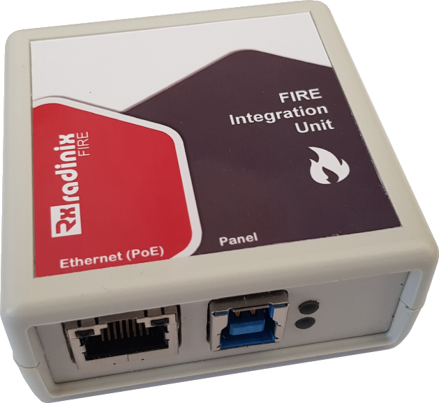 |
Ports available
The device has two ports: Panel and Ethernet. The Panel port has the same look as a USB 3 type B port, but note that it is not a USB port. Do not plug the Radinix device into a USB port or damage may occur to either the device or the port.
Powering the device
The Radinix device uses 802.3af 48V Power over Ethernet (PoE) to function. Please make sure that the PoE adapter is compliant. The lights will immediately flash to indicate start-up and the power light will remain on to indicate online status.
Device setup
Onboard site
We have included an onboard configuration webpage on the Radinix device.
Login Security
The Radinix device uses password authentication. Make sure to make use of strong passwords.
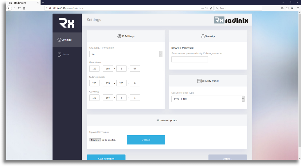
Configuration
You can configure the networking options on the following screen.
Quick help
This links to the quick-help section of the Radinix Intrusion Unit, which can be used as a reference to set up the device in Milestone and Licensing Information.
Defaults
Default IP: 192.168.5.97
Default subnet: 255.255.255.0
Default Gateway: 192.168.5.1
Default Password: admin
Default panel: Tyco IT-100 (select the panel you are connecting to)
Radinium Fire Panel Integration QuickStart Guide
We are proud to have you with us and we hope you receive all the assistance you desire when using our Radinium Fire Panel Integration. We’ll cover topics in the Milestone XProtect® Management Client such as getting your first License for your Radinix Fire Panel, along with its configuration, configuring its Fire Devices, such as call points and smoke detectors, and linking them with cameras, setting up databases and setting up your workflow. We’ll further cover using the Milestone XProtect® Smart Client for viewing triggered alarms, working through the configured workflow and generating alarm and maintenance reports.
Prerequisites
- Milestone XProtect® Management Client 2018 or later installed.
- Milestone XProtect® Smart Client 2018 or later installed.
- Milestone XProtect® Event Server installed and running.
- Radinix Fire Panel Integration Plugin for Milestone XProtect® installed.
To remember:
- The Event Server needs about 5 minutes to update the Radinix status, if the Radinix MINI are used. The intruder alarms will only work after the changes have been propagated through to the Event Server, 5 minutes after completion of the Radinix MINI changes.
- Check licences of all Radinix MINI units. They will not function correctly without being licensed.
QuickStart
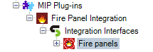
Once you have fulfilled the prerequisites, you can open the Milestone XProtect® Management Client and in the Site Navigation (left pane) navigate to and expand MIP Plugins. At this point you should see the Radinium Fire Panel Integration icon with its label.
![]()
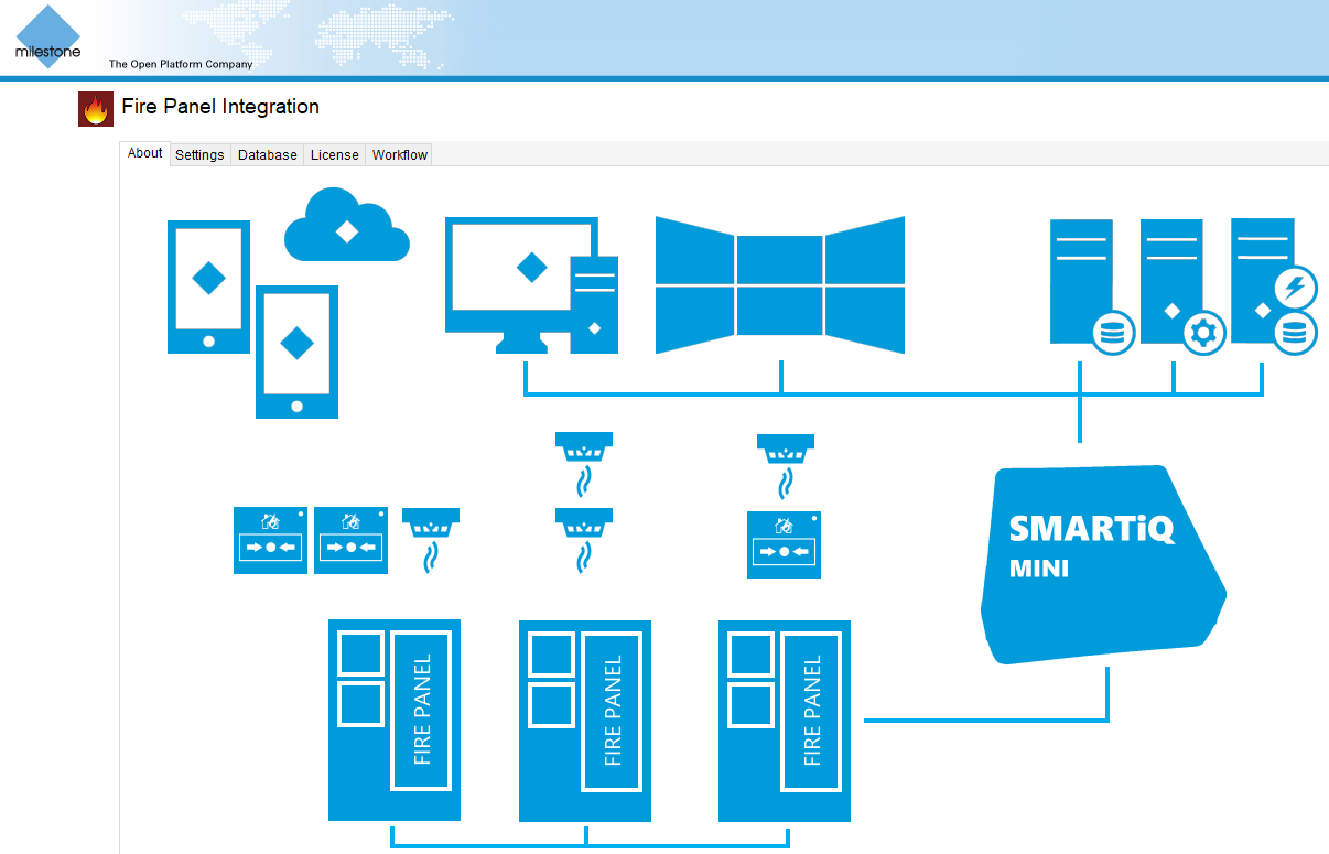
Click on the Radinium Fire Panel Integration menu item and you will see the About page of the Radinium Fire Panel Integration system.
Licensing
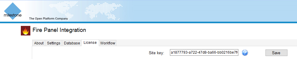
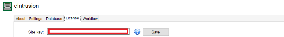
Before commencing any form of setup, you must first sign up and log in to the Radinium licensing web portal. On your User Account Page, you will find your site key.

Copy and paste this site key into the Radinix Fire Panel Integration plugin on the Milestone XProtect® Management Client.
Panel and device setup
Scanning Radinix Fire Panels
In the Site Navigation, expand Radinium Fire Panel Integration and click on Radinixes to find our Radinix scanning utility.
In the Network Address field, populate the IP range (first 3 parts of IP address e.g. 192.168.0 ) and then click on Scan Radinixes. This procedure may take a while depending on the network architecture and, if your device is found before the scan has ended, you may click on Stop Scan. Once it has completed, select the Radinixes that you wish to have configured and then click on Add Configuration. If you are not using a Radinix Fire, right click on Radinixes and manually configure the IP Address of your Fire Panel interface that is supported. Currently supported is Ziton ZP3 on the Radinix interface, Edwards EST3 using BACNet or the Ziton ZP2 on the Modbus protocol.
Once it has completed, select the Radinixes or other integration method that you wish to have configured and then click on Add Configuration.
Radinix Fire Panel Configuration
Click on Fire Panels nested under Radinixes in the left pane.
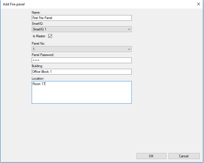
Expand Fire Panels in the secondary left pane and right-click on your newly added Radinix device and Add New. Populate the details of your Radinix Fire Panel, including its password for interfacing. For more information on any of the fields required, simply hover over the label of the field and a popup with more details will appear.
Once all the information has been completed, click OK and the Save icon in the top- left of the management client. All Radinix Fire Panels are required to be licensed for our integration and you may be prompted with 2 messages regarding the state of your licence, depending on whether you have available licenses. Offline checking is done to verify whether you have an existing license within your setup and, if not, then an online check is completed to download any available licenses. Without a license, parts of our product may not function as you would expect.
Radinix Fire Device Configuration
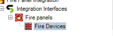
In the Site Navigation expand Fire Panel Integration -> Radinix -> Radinix Fire Panels -> Radinix Fire Devices.
In the secondary left pane expand Radinix Fire Devices. Right-click on your Radinix Fire Panel, click Add New and the Add Radinix Fire Device window will appear.
Once all the information has been completed, click OK and the Save icon in the top- left of the management client. If you are uncertain of the meaning of any of the fields, hover over them and more details will appear.
CSV import of settings
Manual setup of a large number of devices can be quite labour-intensive, so, for that case CSV, import functionality is ideal to add a number of Radinix devices and panels simultaneously. See the CSV File Format page for further details.
Licensing
Welcome to the licensing documentation, where we will give you more details for keeping your panels licensed and therefore fully functional. Please note that the integration plugin will not work for an unlicensed panel.
Licence types
Currently, three types of licences are available to work with our software.
Grace
The Grace license enables the intrusion panel integration software to work for 30 days, by default. The functionality is unlimited and hence this licence serves as a standard Software licence. A Grace license is automatically generated for intrusion alarm panels that have been configured via the cIntrusion plugin in the Milestone XProtect® Management Client.
Software
The Software license permits the full functionality of our plugin and will not expire.
Support
The Support license is an additional licence that adds to the software licence functionality. This licence is optional and is required to maintain a support relationship with cSMART and automatically allows updates to the latest software and firmware versions. The support relationship allows third parties to gain access to support with regards to our security panel integration plugin.
License portal
All licensing is maintained on the License Portal, a website portal accessible at http://portal.radinium.com, which enables an overview of your account and its associated licences. All valid licences are issued from the License Portal. The cIntrusion integration plugin makes provision via online or offline methods for acquiring licence keys, discussed below.
Licensing
Before commencing any form of licensing, you must first sign up and log in to the Radinium licensing web portal. On your User Account Page, you will find your site key.
Copy and paste this site key into the security panel integration plugin on the Milestone XProtect® Management Client.
NB: Do not give this site key to anyone.
You can now select multiple Security Panel items from the licensed and unlicensed lists.
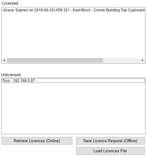
Upon selection, the Online and Offline licensing buttons will activate.
Online Licensing
Generally, licences are obtained using this mechanism of licensing, which requires the Milestone XProtect® Management Client has connectivity to the License Portal. When saving a new Intrusion Panel configuration, this mechanism is automatically triggered to obtain any available licences. In the event that an Intrusion Panel is configured and licensed for the first time with no available licences, a Grace license will be generated on the License Portal, upon retrieval.
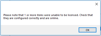
In the event that connectivity was not obtainable during the saving of your configuration, you may be prompted with a message stating this.
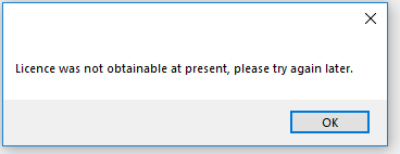
Make sure your Site Key was entered into the Milestone XProtect® Management Client and check whether you have connectivity to the License Portal before trying again.
If you are prompted with a message stating that your device could not be reached, ensure that your Intrusion Panel is on the same network and that the configuration is correct.
Offline Licensing
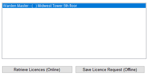
Offline Licensing enables the licensing of Intrusion Panels where there is no connectivity to the Milestone XProtect® Management Client. When using this mechanism, simply select your licences from the licence list and then click the Offline button and you will be prompted to save a License Request Code file to disk.
Navigate to https://portal.radinium.com/dashboard and upload your Licesne Request Code using the Manual License Request file upload.
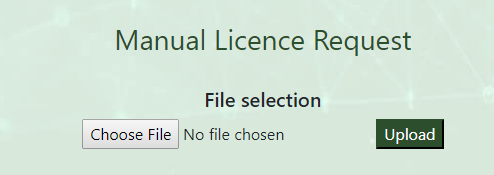
Upon upload, you will be prompted to save your licences file. Select the Load Licenses button on the Milestone XProtect® Management Client, which will be prompted to select your licences file.
![]()
Your previously selected Intrusion Panel items will now be licensed.
Management Client
Welcome to the Radinium Fire Panel Integration Management Client documents where we will supply you with more details on the configuration of an environment.
Camera configuration
Milestone XProtect® primarily focuses on surveillance and serves as a video management system (VMS), allowing for the configuration of cameras out of the box. The Radinix Fire Panel Integration plugin allows those cameras to be associated with each of the Security Zones that you configure for your environment. This guide is intended only to show basic configuration of cameras, however, for further information you may view the Milestone XProtect® documentation.
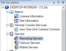
In the Milestone XProtect® Management Client, in the site navigation on the left pane, select Servers -> Recording Servers.
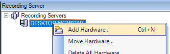
In the Recording Server pane, expand the Recording Servers, right-click on your recording server and select Add Hardware.
At this point, you will be prompted by the Milestone XProtect®’s wizard to add hardware.
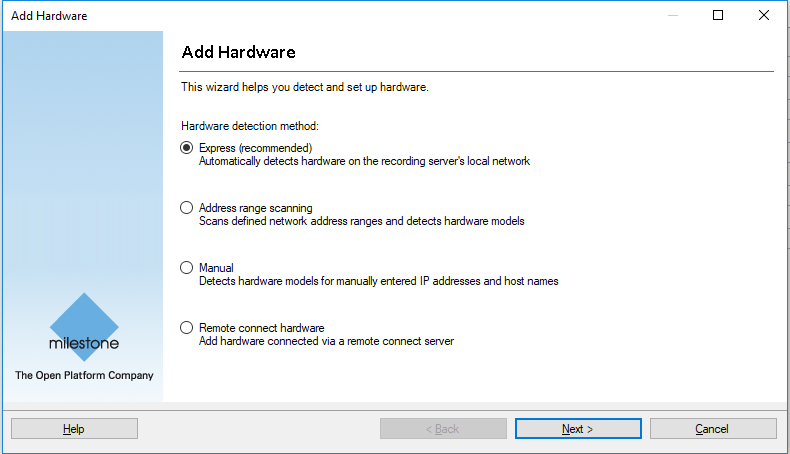
Use any of the provided methods to add your IP Cameras. All cameras that are configured will become available to you when setting up your Fire Devices.
Users & Security
The Radinix Fire Panel Integration plugin utilizes the built-in security of Milestone XProtect® and distinguishes between two types of users by exposing a new role: the Fire Supervisor. The Fire Supervisor role gains two permissions: Fire Panel Viewer and Fire Panel Supervisor.
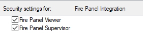
Fire Panel Viewer
A fire panel viewer is given the ability to view alarms in the Milestone XProtect® Smart Client. This permission is intended for standard operators.
Fire Panel Supervisor
A fire panel supervisor is given the ability to close alarms in the Milestone XProtect® Smart Client. This permission is intended for staff allowed to monitor and manage the operators.
Configuration
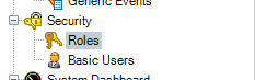
To add/remove users to the Fire Supervisor role, in the the site navigation on the left pane, expand Security and select Roles.
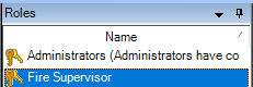
In the Roles pane, select the Fire Supervisor role.
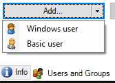
At the bottom of the Role settings pane, the right-most pane, select Users and Groups and click the Add button to add basic users or Windows users.
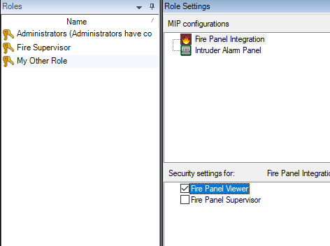
You are also able to add the Fire Panel Viewer and Fire Panel Supervisor permissions to existing roles by navigating to your desired role at the bottom of the Role settings pane and select MIP  .
.
At the top of Role Settings pane, select Radinium Fire Panel Integration.
Now, check the checkboxes of the permissions you would like to add to your alternative role.
Plugin Configuration
When navigating to the Radinix Fire Panel Integration plugin overview, you will be able to configure the various parts of your plugin. For instance: report defaults, database credentials, licensing of panels and your workflow configuration.
Settings
You can add a company logo and disclaimer text that will appear in reports you generate using the cIntruder plugin. The company logo is intended for you to white-label the reports we provide in the plugin, and the disclaimer text will be placed in the footer of each page of your reports.
![]()
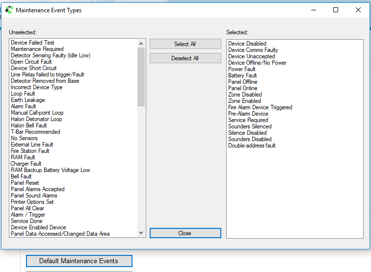
A list of default maintenance events for the maintenance report can be configured by clicking on the Default Maintenance Events button to allow you to personalise your favourite events to be listed in your maintenance report.
Database
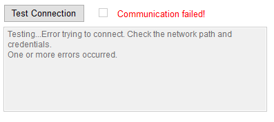
The database tab allows one to set correctly their database credentials and test whether the credentials supplied allow the Radinix Fire Panel Integration plugin access to the database.
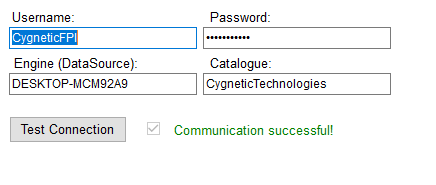
Upon supplying incorrect settings, the resulting error will be displayed in the box under the test status as follows:
License
The license tab allows one to keep their fire panel licences valid in an intuitive manner. We have dedicated a page to describe and assist with licensing. Click through to licensing.
Workflow
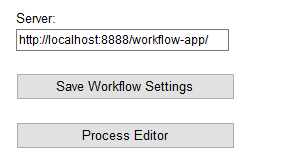
The workflow tab allows configuration of the workflow server and provides a process editor for altering your processes.
Fire Panel Environment Setup
Click on the Radinium Fire Panel Integration menu item and you will see an overview of the environment.
Scanning Radinixes
In the Site Navigation, expand Radinium Fire Panel Integration and click on Radinixes to find our Radinix scanning utility.

In the Network Address field, populate the IP range (first 3 parts of IP address e.g. 192.168.0 ) and then click on Scan Radinixes. This procedure may take a while depending on the network architecture and if your device is found before the scan has ended, you may click on Stop Scan. Once completed, select the Radinixes that you wish to have configured and then click on Add Configuration. If you are not using a Radinix Fire, right-click on Radinixes and manually configure the IP Address of your Fire Panel interface supported. Currently supported is Ziton ZP3 on Radinix interface, Edwards EST3 using BACNet or the Ziton ZP2 on the Modbus protocol.
Fire Panel Configuration
Click on Fire Panels nested under Radinixes in the left pane.
Expand Fire Panels in the secondary left pane and right-click on your newly added Radinix device and then click Add New. Populate the details of your Fire Panel, including its password for interfacing with the Fire Panel. For more information on any of the fields required, simply hover over the label of the field and a popup with more details regarding the field in question will be visible.
Once all the information has been completed, click OK and then click the Save icon in the top left of the management client. All Fire Panels are required to be licensed for our integration and you may be prompted with 2 messages regarding the state of your licence depending on whether you have available licenses. Offline checking is completed to verify whether you have an existing license within your setup and, if not, then an online check is completed to download any available licenses. Without a licence, parts of our plugin may not function as you expect.
Fire Device Configuration
In the Site Navigation expand Radinium Fire Panel Integration -> Radinix -> Fire Panels -> Fire Devices.
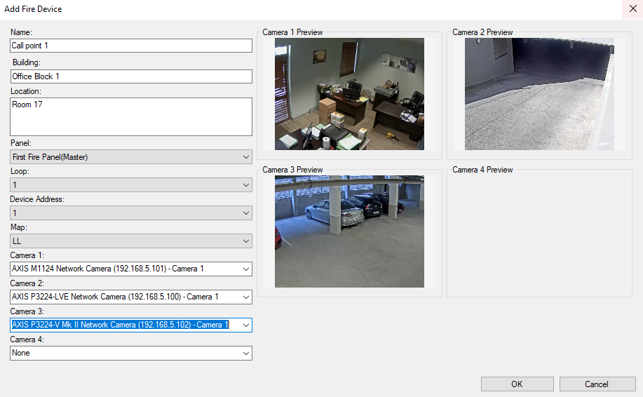
In the secondary left pane, expand Fire Devices. Right-click on your Fire Panel, click Add New and the Add Fire Device window will appear.
Once all information has been completed, click OK and then click the Save icon in the top left of the management client. If you are uncertain of the meaning of any of the fields, hover over them and more details about them will appear.
Import Fire Panel Environment (CSV)
The manual setup of a large number of devices can be quite labour-intensive, so, for that case CSV, import functionality is ideal to add a number of Radinix devices, panels and fire devices simultaneously. See the CSV File Format page for details.
Smart Client
Welcome to the Radinium Fire Panel Integration Milestone XProtect® Smart Client documents, where we will provide more details on receiving fire alarms, participating in the workflow and generating reports.
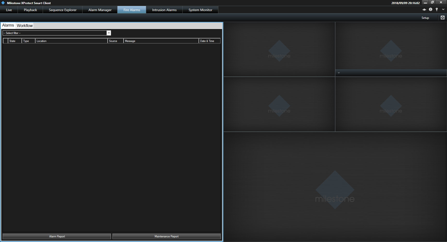
Workspace overview
The Radinium Fire Panel Integration workspace on Milestone XProtect® Smart Client actions alarms raised by fire panels from your environment that have been configured via the Milestone XProtect® Management Client. As such, there are a number of panels for various uses.
Camera Panels
On the top right of the Radinium Fire Panel Integration workspace are 4 panels for Camera 1, Camera 2, Camera 3 and Camera 4 that are associated with an alarm. These cameras are populated into the alarm, depending on which form of alarm is triggered. In the general case, these cameras will be taken from the Radinix Fire Device triggering the alarm, but may also be a best match for the most relevant cameras if the alarm is emitted by the fire panel.

If the cameras that populate these panels support Pan, Tilt or Zoom, it is possible to command the camera on these actions from these panels. It is also possible to replay footage from within these panels.
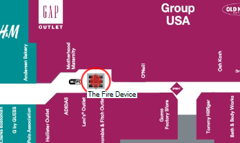
Map Panel
On the bottom right of the Radinium Fire Panel Integration workspace, beneath the camera panels, is a single panel that is used to display a map.

Radinix Fire Devices ![]() can be positioned on the map. Upon an alarm being selected from the Alarm Tab, the map that was associated with the alarm’s source will be displayed.
can be positioned on the map. Upon an alarm being selected from the Alarm Tab, the map that was associated with the alarm’s source will be displayed.
If the alarm is in an Open state and the device has been positioned on the map, a flashing red ring will circle the device on the map.
By double-clicking anywhere on the map, the map will fill the entire workspace for increased visibility. It is also possible to move the map around by click-dragging the map in a particular direction. It is possible to zoom in and out using your mouse scroll up and down respectively.
Alarm Tab
On the left panel, by clicking the Alarms tab, the Alarm tab will be displayed (also displayed by default).
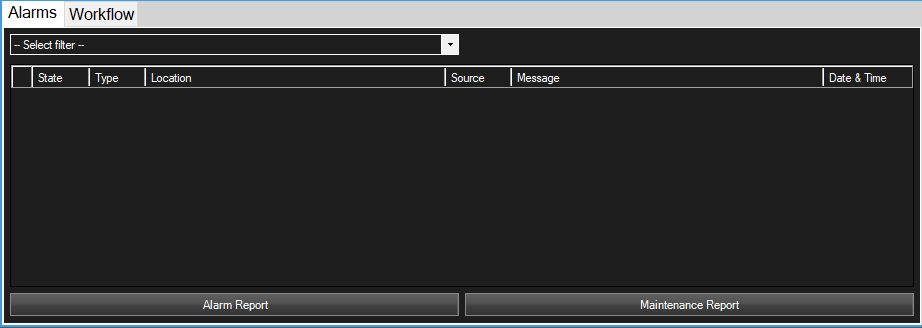
All Fire Panel alarms that are triggered are viewable from the Alarm tab in the Radinium Fire Panel Integration workspace.
It is possible to double-click on the gray area on the right of the tab headings (Alarms, Workflow) to make the Alarm tab fill the workspace, in order to allow more details of each alarm line to be seen.
The following table defines the list of details available for each alarm line.
| Column Name | Description |
|---|---|
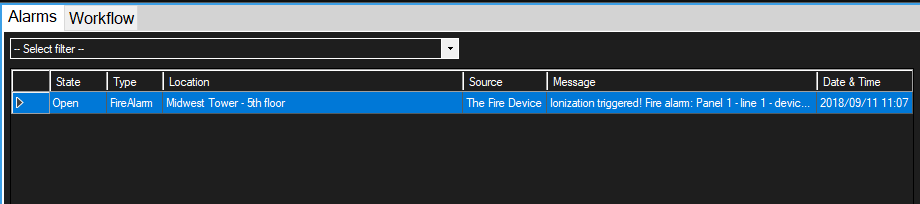
| State | The state this alarm is in, either Open to indicate an alarm is new, In Progress to indicate that someone has acknowledged this alarm or Closed to indicate this alarm has been dealt with. |
| Type | The type of alarm that was triggered, either Fire Alarm for general fire alarms or Double Knock for a double knock alarm. |
| Location | The location where the device triggering this alarm can be found and a guide for where to look for this device. |
| Source | The name of the device that triggered this alarm, either the name of the Fire Device or the name of the Fire Panel if the Fire Device was not configured correctly. |
| Message | A message providing more information to help identify the cause of this alarm. |
| Date & Time | The date and time that this alarm was triggered. |
The Radinium Fire Panel Integration supports the notion of Double Knock events. A double knock event is defined as being more than 1 Fire Device triggering within the same Fire Zone configured on a Fire Panel. These alarms will appear in red on the alarm tab.

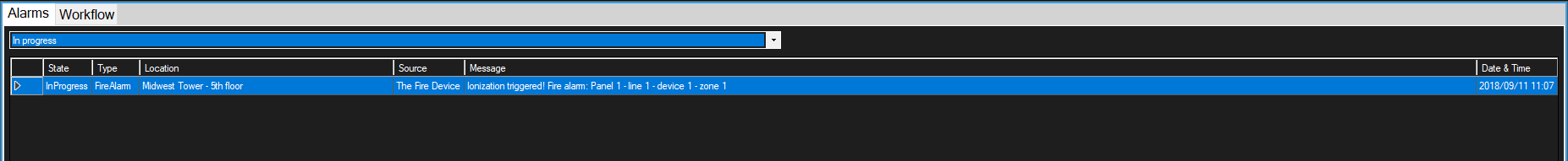
At the top of the Alarm tab under the tab headings is the alarm filter, which allows you to filter the alarms by state, either Open, In Progress or Closed.
A number of actions may be performed on alarms by right-clicking on the alarm line. Depending on the state of the alarm and your privileges, options will populate the context menu.
When an alarm is in the Open state, you may Acknowledge the alarm. Acknowledging the alarm will move the alarm state into an In Progress state. If workflow has been setup and any tasks are available for the workflow you will be automatically switched to the workflow tab and the available tasks will be claimed by you.
When an alarm is in the In Progress state, you may Close the alarm, but only if either no workflow was setup or there are no tasks for the process instance linked with this alarm. If workflow has been setup and tasks are available for the process instance of this alarm, you may Switch to workflow, which will take you to your current tasks for this alarm within the workflow tab.
Alarm Report
To generate a report on the alarm events that have already triggered, click on the Alarm Report button at the bottom of the alarm tab. You will be presented with a popup window as follows:
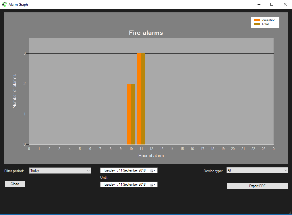
Notice that the alarms are categorised by their device type that emitted the alarm, in the image above Ionization. Only the 5 categories with the most alarms will be grouped. Total will contain all alarms for all device types including and excluding the 5 top categories. The top right corner of the graph contains a legend that indicates the colours for each device type category.
The graph is generated dynamically as one changes the filtering options at the bottom of the graph.
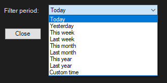
Starting from the left, we have a Filter Period, which are predefined periods: Today, Yesterday, This Week, Last Week, This Year, Last Year and Custom Time.
Upon selecting any of these filters, the From and Until dates situated in the center below the graph will be adjusted appropriately.
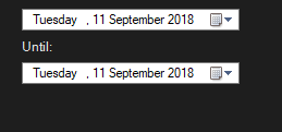
These dates may be adjusted as you desire.
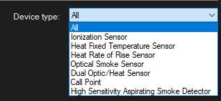
Below the alarm report on the right side is a Device Type filter.
The Export to PDF button will generate a PDF containing the displayed graph according to your filter options and will also include a row for each alarm in a table. If configured in the Milestone XProtect® Management Client Fire Panel Integration settings, the PDF report will also contain your custom logo in the header as well as your disclaimer in the footer.
Click here to view an example report
Maintenance Report
To generate a report on the maintenance events that have already occurred, click on the Maintenance Report button at the bottom of the alarm tab. You will be presented with a popup window as follows:
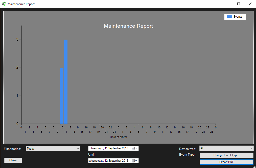
The graph is generated dynamically as one changes the filtering options at the bottom of the graph.
Starting from the left, we have a Filter Period, which are predefined periods: Today, Yesterday, This Week, Last Week, This Year, Last Year and Custom Time.
Upon selecting any of these filters, the From and Until dates situated in the center below the graph will be adjusted appropriately.
These dates may be adjusted as you desire, but be aware that only 400 days of data are stored by default.
Below the maintenance report on the right is a Device Type filter.
Below the Device Type filter on the right is a Event Type filter.
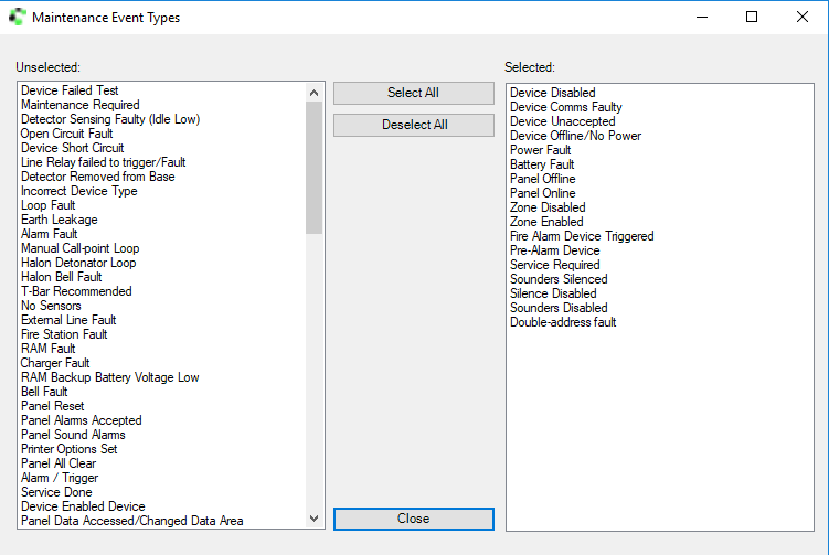
The default event types are populated from the list of event types that were configured for Fire Panel Integration plugin within the Milestone XProtect® Management Client. Double-click on an event type in the Unselected column to have it moved to the Selected column. Having no events selected will result in the same report when having all events selected, i.e no filtering shall bring up all events.
The Export to PDF button will generate a PDF containing the displayed graph according to your filter options and will also include within a table a row for each alarm. If configured in the Milestone XProtect® Management Client Fire Panel Integration settings, the PDF report will also contain your custom logo in the header as well as your disclaimer in the footer.
Click here to view an example report.
Workflow Tab
There are two ways to get to the Workflow tab. You can access the workflow tab by clicking on Workflow at the top right of the Fire Panel Integration workspace.
Or you are able to right-click on an alarm that is In Progress and still has tasks available, and click on the Workflow context menu item. When using the alarm context menu, only tasks for the process instance associated with the selected alarm will be displayed.
You can expand the tab by double-clicking on the grey bar at the top on the right next to the Workflow tab.
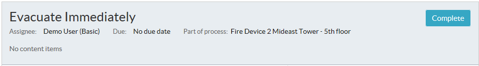
Responsibility for each User Task in the workflow requires to be claimed before participating in any activity on that task, which can be done by clicking the Claim button on the top right in the activity panel heading.
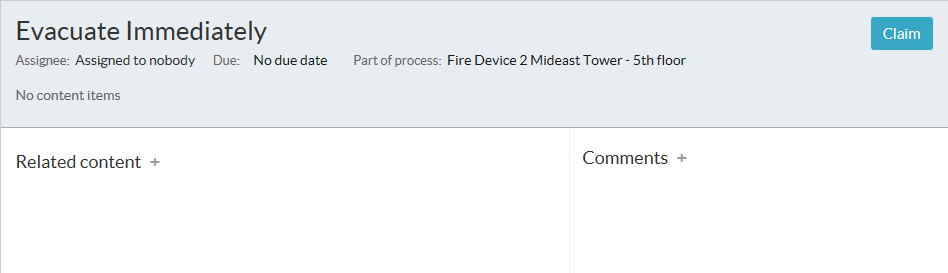
In the above image of the activity panel, there is space for communication on the right and adding relevant content files on the left. These features promote collaboration around the task by allowing these comments and files to be seen by any users who are involved with the task.
Each user task may or may not have a form associated with it and each form may offer a set of outcomes for that User Task. Some forms will have required fields which are outlined in red, which need to be filled before allowing the outcome buttons to become clickable. The following image shows an outcomes-based form with Yes and No options grayed out as the form has a required field that has not been filled in.
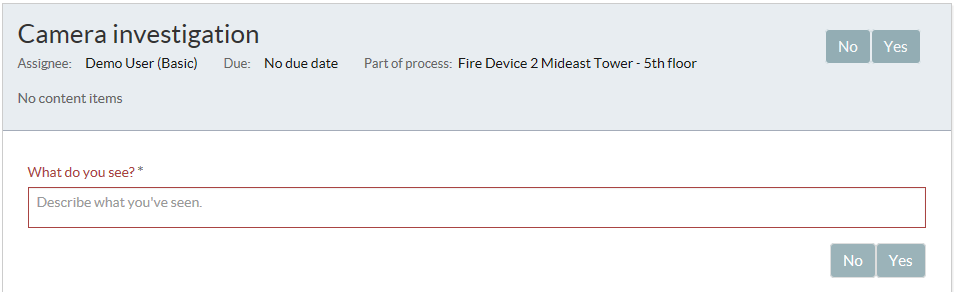
In the case of a User task with no outcomes, a Complete button will be displayed.
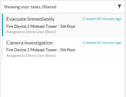
In the task list on the left, you can open filtering options by clicking on the filter icon. 
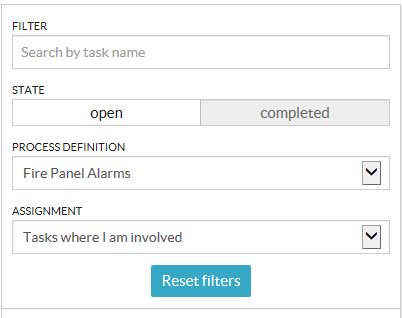
By changing any of these options, the newly-filtered list of tasks will become available.
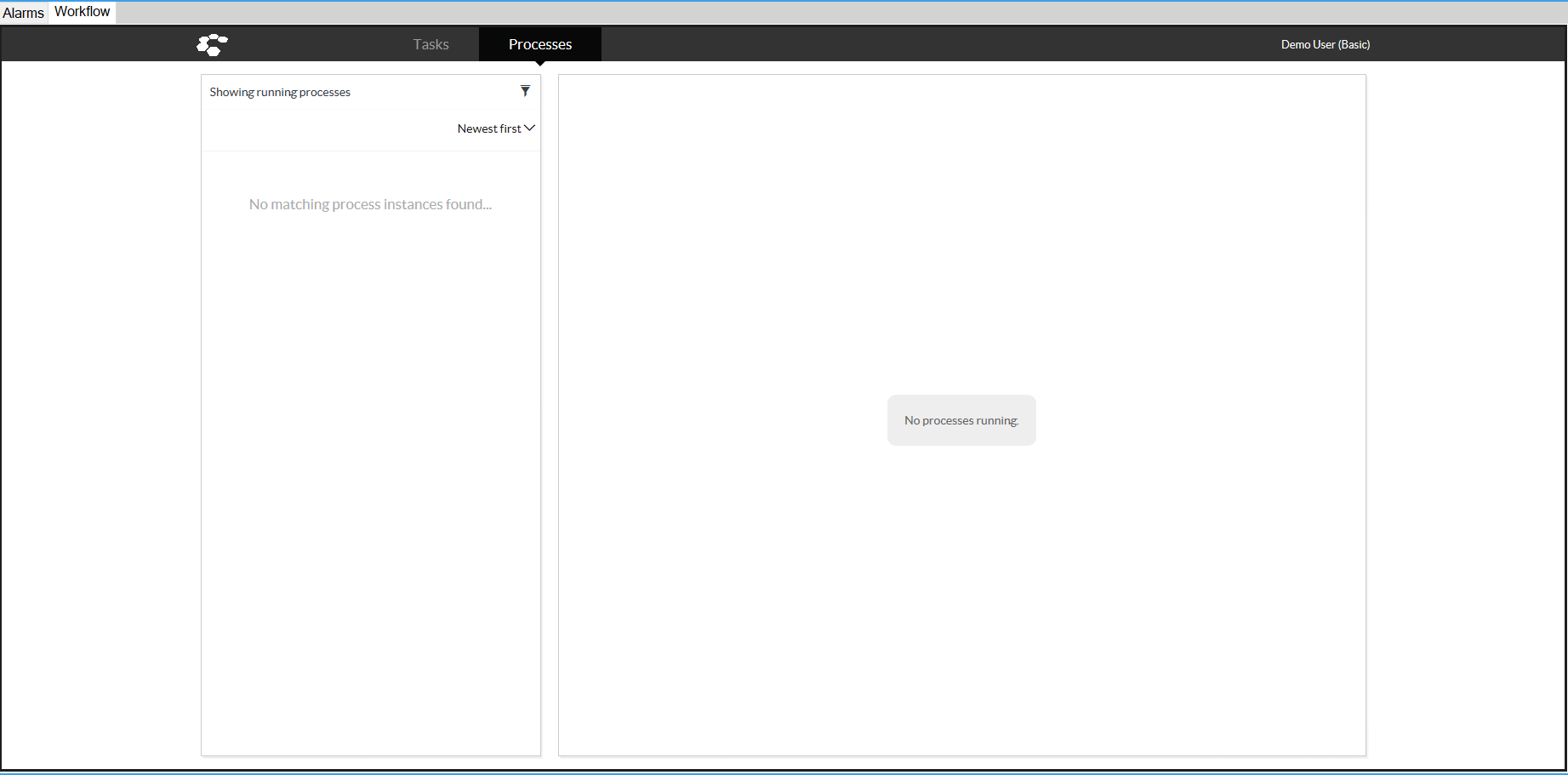
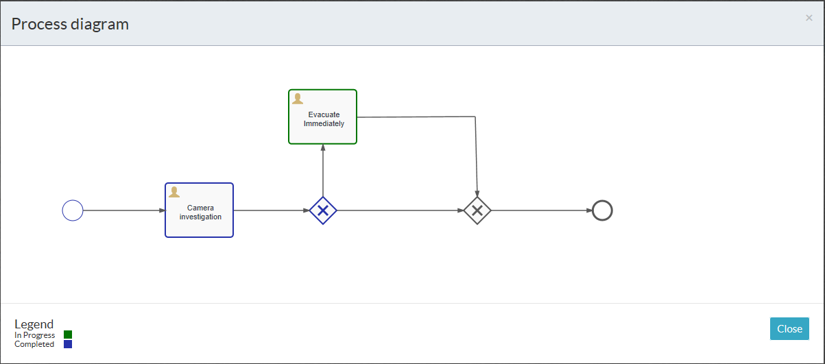
The auditability of the process-engine allows processes to be viewed in fine detail at any stage of the process by navigating to Processes in the Workflow tab. One is able to see the currently active task, a list of completed tasks beneath it and general comments can be made regarding the process.
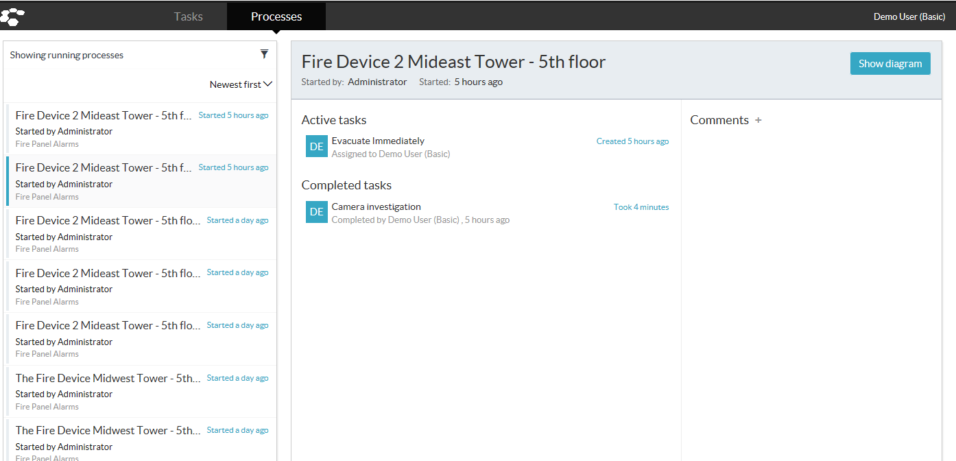
By clicking on the Show Diagram button, you can see where, within the process, your current active task is. Completed tasks are outlined in blue and the current task is outlined in green.
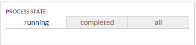
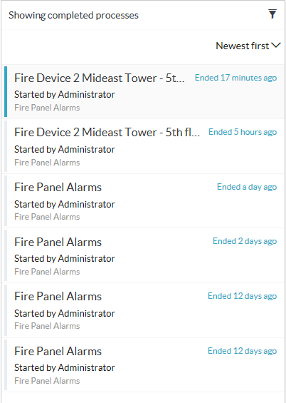
To view the completed processes, click on the Filter icon at the top right in the process list.
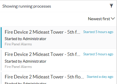
Select the Completed state from the list of process states and the list will be populated with completed processes. You are also able to view processes in all states.
Workflow
Welcome to the Radinium Fire Integration Workflow documentation, where we will provide more details on the configuration of a workflow process.
BPMN 2.0
Business Process Model Notation (BPMN) has been developing over a number of years, releasing its first version in March of 2007. BPMN now sits on version 2.0, released in January of 2011, with one of its primary improvements facilitating the storage of process templates and data.
Radinium has included BPMN 2.0 in all our integration releases, thereby increasing efficient auditing, coordination and collaboration of business processes and their tasks. We want the user to have the ability to define how the security alarm processes within their premises are managed, as they see fit; an increasingly important capability when working within a mission-critical environment, where pressure can arise during the execution of a process, causing potential panic and mistakes. Radinium’s process engine is there to keep your processes executing with integrity.
Terminology
| Term | Definition |
|---|---|
| Claim | An action a user takes to claim responsibility for a task. By claiming a task, no other user can claim the task. This helps with coordination of User tasks. |
| Form | A data-capture mechanism that supports various inputs from users. Generally, a form is created to be associated with a User Task. The process engine stores the data that is captured for later use in the process instance. The captured data can also be used for auditing and reporting purposes even after a process instance ends. |
| Process | A template of a Process Instance that is usually represented as a visual diagram, but has underlying data that conforms to BPMN2.0. |
| Process Engine | The software product designed to support and run processes defined in BPMN2.0. |
| Process Instance | An instance of a Process. The process plan is defined by the process and will contain all relevant elements and forms as defined by the process. |
Supported Subset
As BPMN 2.0 has a wide array of notation to facilitate just about every kind of process, we have narrowed down a subset of the notation that is most commonly used. Upon request, we are able to extend this subset to include any part of BPMN 2.0 that you may require.
Start events
| Name | Description | Notation |
|---|---|---|
| Start Event | Defines an entry point into your process model. At least 1 start point is required in your process. |  |
Activities
| Name | Description | Notation |
|---|---|---|
| User Task | Defines a task that requires a user’s input. This is usually accompanied by a form that captures data about the task to be used later within the process or for auditing/reporting purposes. |  |
| Service Task | Defines a task that is executed automatically as software in the background when this task becomes active. An example would be to automatically silence a panel without further human intervention. |  |
Gateways
| Name | Description | Notation |
|---|---|---|
| Exclusive Gateway | Is used for conditional flow where only 1 path may be followed, depending on which path’s conditions are met. This gateway is also used to consolidate multiple execution paths from an exclusive gateway into one path. |  |
| Inclusive Gateway | Is used for conditional flow where multiple paths may be followed, depending on whether the conditions for each path are met. This gateway is also used to consolidate multiple execution paths into one path. |  |
| Parallel Gateway | Is used for allowing 2 or more tasks to be active simultaneously, whereby multiple users can claim and complete those tasks in any order. This is synonymous to an AND logical gate. This is also used to consolidate multiple executions’ paths into one path. |  |
End events
| Name | Description | Notation |
|---|---|---|
| End Event | Defines a point within your process that terminates the process instance. This will make further tasks within the process unclaimable and incompletable. |  |
Process Editor
Creating your workflow
To fully harness the power of BPMN 2.0, we’ve included the ability for you to alter and illustrate workflows directly from within Milestone XProtect® Management Client.
In the Site Navigator, expand MIP Plugins and click on Radinium Fire Integration menu item.

Click on the workflow tab in the Radinium Fire Integration panel.
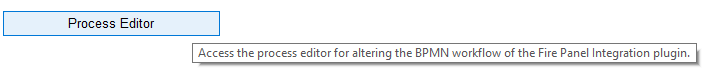
Click on Process Editor.
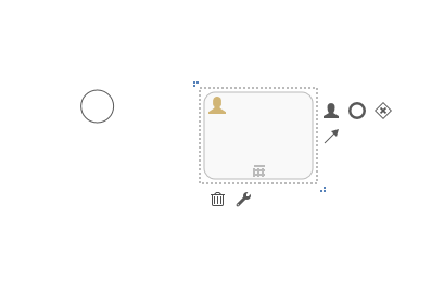
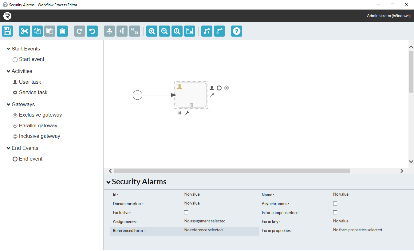
An initial canvas that has not yet been altered will look as follows. Click on the canvas to display it at the bottom of the property menu for the workflow process.
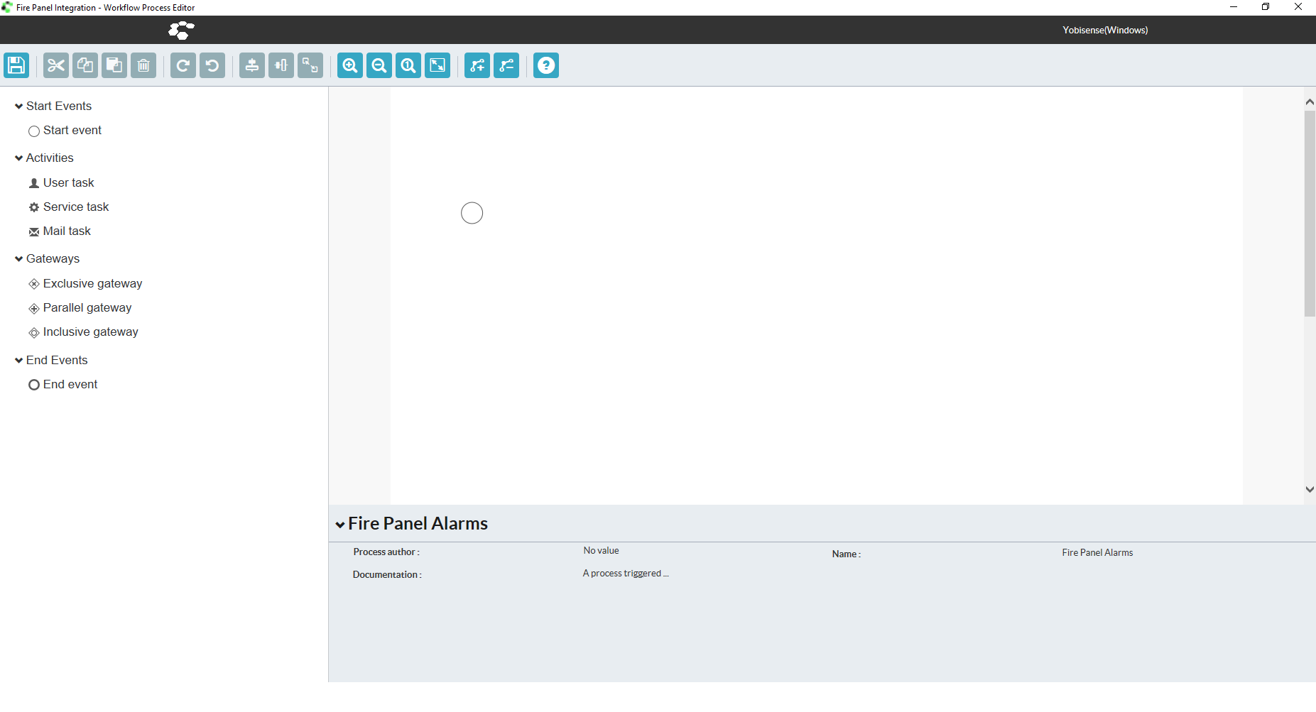
Add a new notation to your BPMN 2.0 workflow simply by clicking and dragging any of the items from the toolbox on the left onto the canvas.
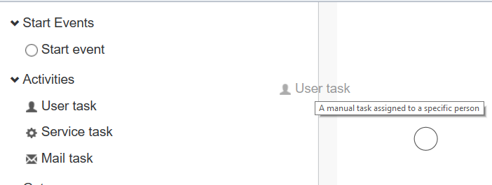
Upon releasing the item on the canvas, a representation of the notation will appear in that position. You can drag these objects around the canvas freely.
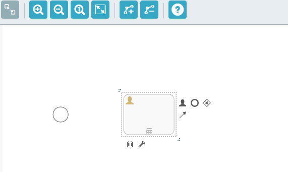
To link one object to the next, click on the source object, now click and drag the Sequence flow icon ![]() onto the center of your destination object.
onto the center of your destination object.
![]()
Upon dropping the arrow icon on the destination object, a sequence flow will be created between the source and destination.
![]()
Adding forms to user tasks
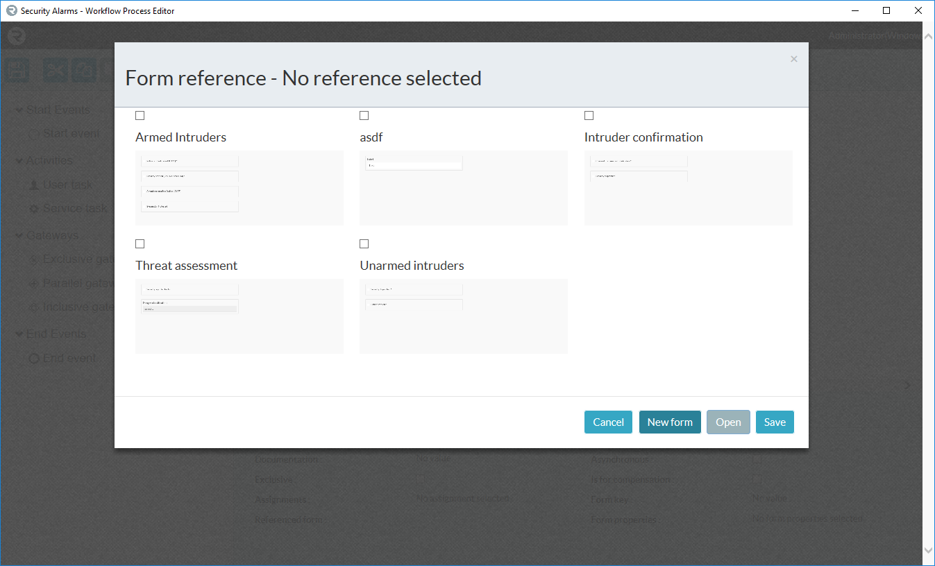
First, create a form by clicking on the Referenced Form text at the bottom of the page when a user task is selected.
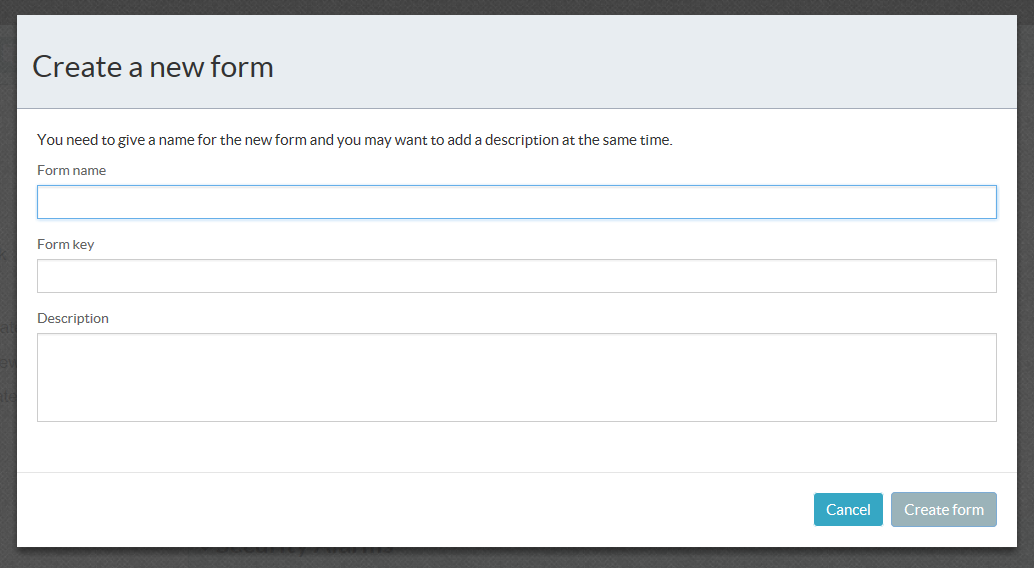
Click the New Form button to create a new form, or select a form that needs to be modified and click Open.
Fill in the name and form key. Please remember that the form key should not contain spaces or special characters.
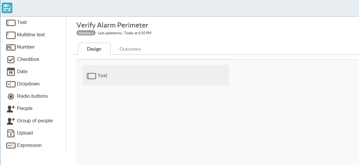
A new form looks like the below image:

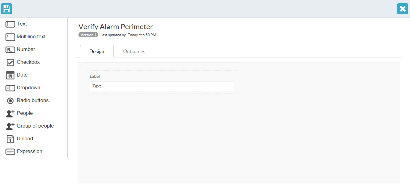
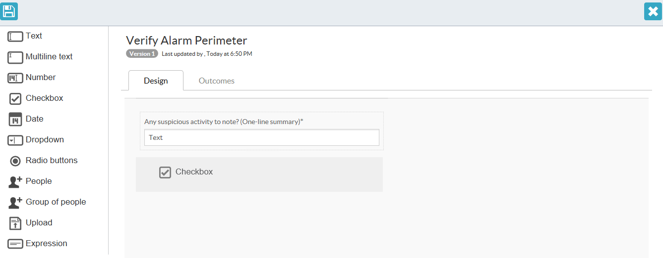
You can drag and drop fields on the form from the left-hand menu.
The field appears after drag-and-drop completes.
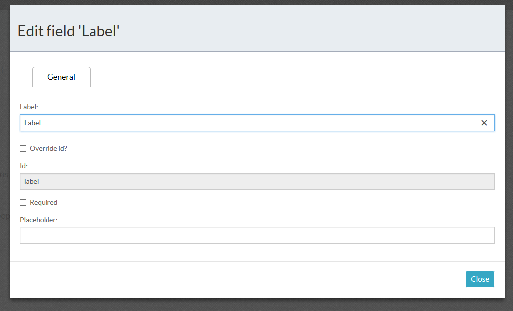
If you hover over the field, you have options to either modify settings or to delete the field.
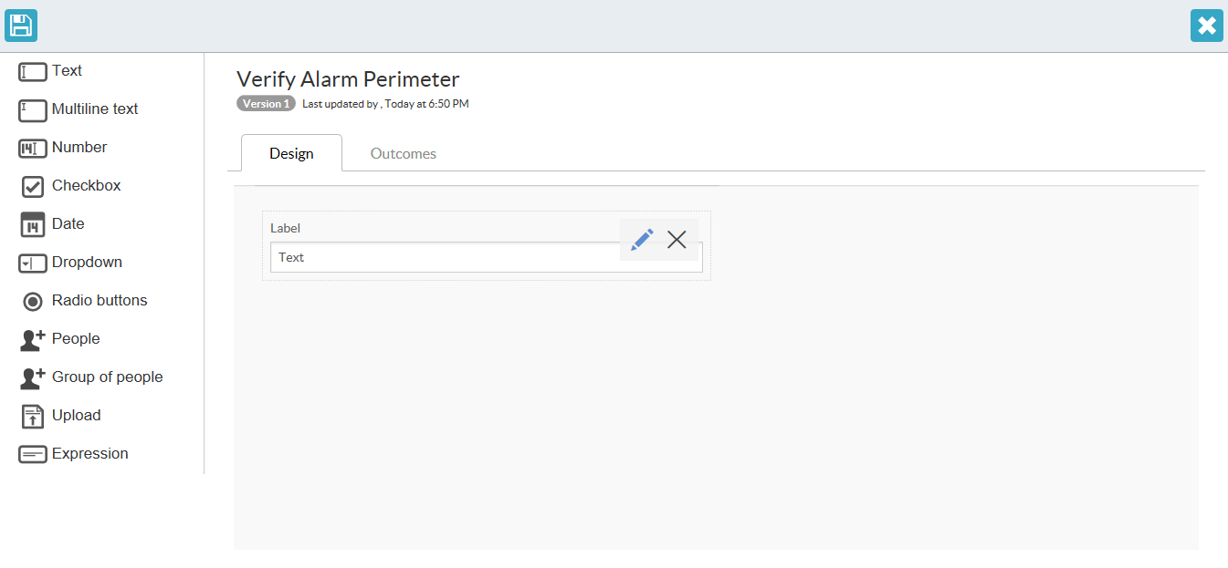
Each field has different settings which you can modify. The Required label means that the field needs to be filled in for the form to be completed.
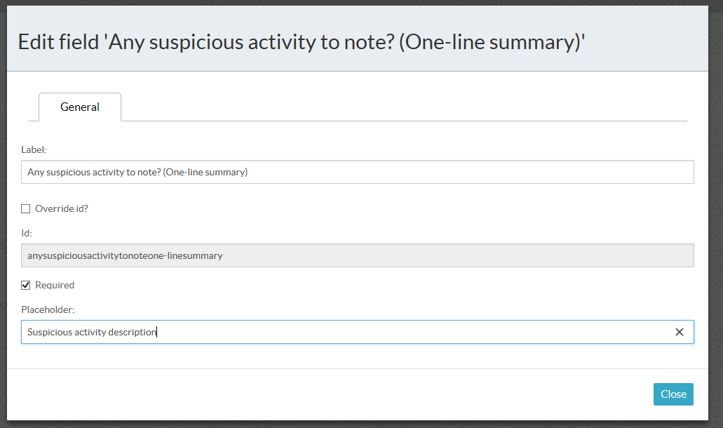
You can add additional fields to the form as needed.
Remember to save the form when done. Click on the save button on the top-left of the window.
Each form element has different options, for example the dropdown has options that can be pre-set so that they are available to select.
Object Properties
Gateways
Exclusive Gateway
Accessed by clicking on any exclusive gateway object on the canvas.
| Property | Description |
|---|---|
| Asynchronous | Makes this exclusive gateway execute asynchronously, allowing the workflow to continue whilst this exclusive gateway is executed. |
| Documentation | The exclusive gateway allows flow through it to continue to only a single outgoing element of the options outgoing from it. The conditions on the outgoing arrows will be evaluated to help determine which outgoing flow will be followed. |
| Exclusive | Marks this exclusive gateway as executing in exclusivity. Elements marked as exclusive within a workflow never execute simultaneously and execute in a first in, first out manner. |
| Flow Order | The order in which to process the outgoing sequence flows. Only 1 will execute. |
| Id | A unique identifier for this exclusive gateway element within the BPMN 2.0 xml document. |
| Name | The descriptive name of this exclusive gateway element within the BPMN 2.0 xml document. |
Inclusive Gateway
Accessed by clicking on any inclusive gateway object on the canvas.
| Property | Description |
|---|---|
| Asynchronous | Makes this inclusive gateway execute asynchronously, allowing the workflow to continue whilst this inclusive gateway is executed. |
| Documentation | The inclusive gateway allows one or more outgoing flows to execute. The conditions on the outgoing flows will determine whether the outgoing flow is executed or not. |
| Inclusive | Marks this inclusive gateway as executing in exclusivity. Elements marked as inclusive within a workflow never execute simultaneously and execute in a first in, first out manner. |
| Flow Order | The order in which to process the outgoing sequence flows. One or more will execute. |
| Id | A unique identifier for this inclusive gateway element within the BPMN 2.0 xml document. |
| Name | The descriptive name of this inclusive gateway element within the BPMN 2.0 xml document. |
Parallel Gateway
Accessed by clicking on any parallel gateway object on the canvas.
| Property | Description |
|---|---|
| Asynchronous | Makes this parallel gateway execute asynchronously, allowing the workflow to continue whilst this parallel gateway is executed. |
| Documentation | The parallel gateway allows multiple simultaneous outgoing flows to execute at the same time. The gateway allows all of the outgoing flows to run at the same time. |
| Parallel | Marks this parallel gateway as executing in exclusivity. Elements marked as parallel within a workflow never execute simultaneously and execute in a first in, first out manner. |
| Flow Order | The order in which to process the outgoing sequence flows. One or more will execute. |
| Id | A unique identifier for this parallel gateway element within the BPMN 2.0 xml document. |
| Name | The descriptive name of this parallel gateway element within the BPMN 2.0 xml document. |
Sequence Flow (the arrows between the elements)
Accessed by clicking on any sequence flow object on the canvas.
| Property | Description |
|---|---|
| Documentation | A few lines of text describing the purpose of this sequence flow, or any extra details required to help understand this sequence flow. |
| Default Flow | Marks this sequence flow being the default if no other flow was followed. Can’t be used in conjunction with Flow Condition. |
| Flow Condition | A condition that is set when matching whether to execute this sequence flow or not. Can’t be used in conjunction with Default Flow. |
| Id | A unique identifier for this sequence flow element within the BPMN 2.0 xml document. |
| Name | The descriptive name of this sequence flow element within the BPMN 2.0 xml document. |
How to use conditional flows and gateways
Form outcomes
To create an outcome for a form, when the form has been completed, select the Outcomes tab at the top of the form. Add outcomes to the form to be able to access it from the process flow.

Click on Add Outcome until the different outcomes are added. Remember that an outgoing flow can only have a single outcome. 
Sequence conditions
To select the necessary task to be run, use the Flow Condition field on the sequence flow that goes out from the gateway. Assuming the previous entry was a form that has outcomes, the outcome will have a text value.

Note that the text is shortened in the bottom block. The condition selector will appear when the above has been clicked.

Select the form outcomes with the dropdown to set the flow conditions.

To combine multiple flows into a single flow, use the appropriate gateway.
- To wait for all incoming tasks until they all have completed, use a Parallel Gateway. This ensures that all incoming tasks have completed before continuing with the process after the gateway. This is similar to the incoming behavior of the inclusive gateway.
- To wait for any incoming task until it has completed, use an Exclusive Gateway. This assumes that a single task will have completed before continuing the process flow path.
Process Definition (Workflow)
Accessed by clicking on any piece of blank canvas.
| Property | Description |
|---|---|
| Description | A few lines of text describing your workflow’s purpose, or any extra details required. |
| Name | The name you would like to call your workflow. |
| Process Author | The author of your workflow. |
Service Task
Accessed by clicking on any service task object on the canvas.
| Property | Description |
|---|---|
| Asynchronous | Makes this service task execute asynchronously, allowing the workflow to continue whilst this task is executed. |
| Class | A class reference that implements the service task logic. |
| Class Fields | Fields of the class that are set for this process instance. |
| Delegate Expression | Service task logic defined as a delegate expression. |
| Documentation | A few lines of text describing the purpose of this service task, or any extra details required to help understand this service task. |
| Expression | Service task logic defined as an expression. |
| Exclusive | Marks this service task as executing in exclusivity. Tasks marked as exclusive within a workflow never execute simultaneously and execute in a first in, first out manner. |
| Id | A unique identifier for this service task element within the BPMN 2.0 xml document. |
| Name | The descriptive name of this service task element within the BPMN 2.0 xml document. |
| Result Variable Name | A variable within the process instance to store the result of the service task. |
We have provided different preset service tasks for use: Security Panel Accept, Security Panel Silence and Security Panel Reset. To implement the accept, use as Class the words “radinium.workflow.fpi.Accept”, for silence, “radinium.workflow.fpi.Silence”, and for reset, “radinium.workflow.fpi.Reset”. The panel will only reset when all workflows associated with the panel have been completed. Please note that an indemnity form will need to be filled out before remote management functionality will be exposed (silence/reset/accept). Email: info@radinium.com for further information.
User Task
Accessed by clicking on any user task object on the canvas.
| Property | Description |
|---|---|
| Asynchronous | Makes this user task execute asynchronously, allowing the workflow to continue whilst this task is executed. |
| Documentation | A few lines of text describing the purpose of this user task, or any extra details required to help understand this user task. |
| Form Key | An override of the referenced form’s form key. |
| Form Properties | |
| Exclusive | Marks this user task as executing in exclusivity. Tasks marked as exclusive within a workflow never execute simultaneously and execute in a first in, first out manner. |
| Id | A unique identifier for this user task element within the BPMN 2.0 xml document. |
| Name | The descriptive name of this user task element within the BPMN 2.0 xml document. |
| Reference Form | A reference to a form which will be displayed to the user when the user claims this task. |
Permissions and roles
Welcome to the Radinium Fire Panel Integration permissions and roles documentation where we will describe more details around the configuration of rights and roles for the plugin.
Security settings
Before a user is allowed to access the fire panel workflow system, the user will need appropriate permissions. To allocate permissions to the user, the standard Milestone role system is used.
Allocation of a role
First, navigate to the Security -> Roles menu item on the left-hand panel of the management client.
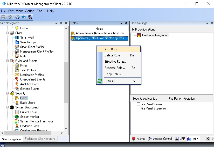
Add a description to the role and click OK.
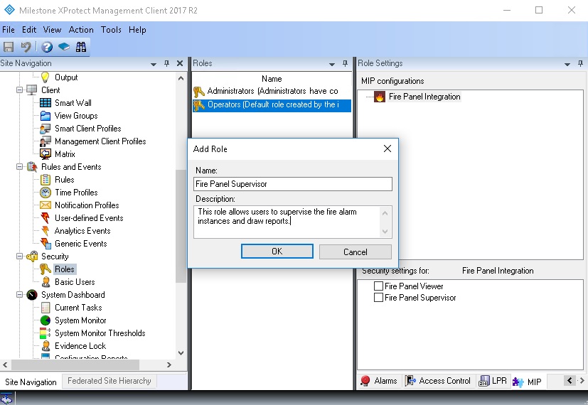
Allocate the security settings for the Radinium Fire Panel Integration plugin under the MIP tab at the bottom right.
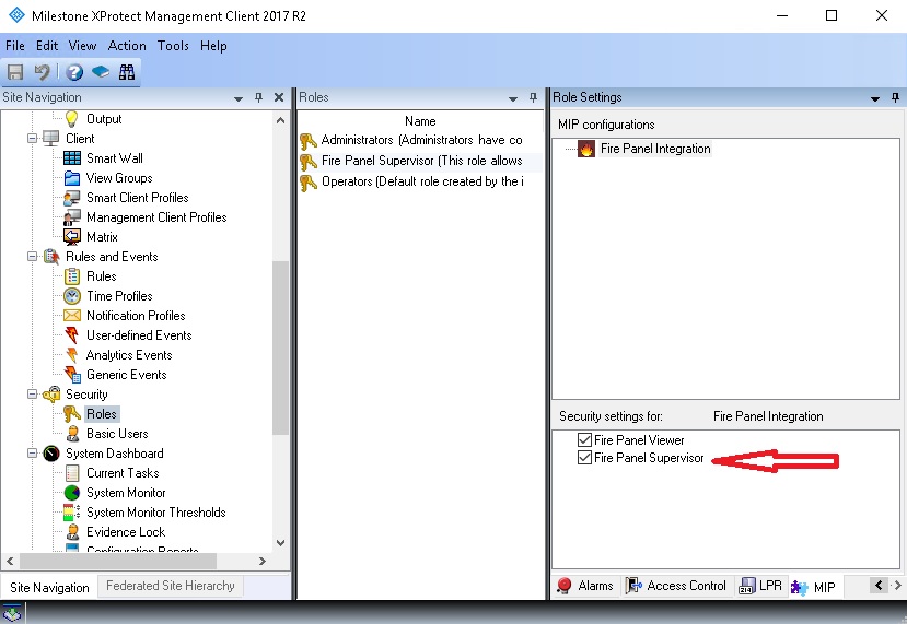
The user now has permissions to access the workflow and manage alarms. To only allow viewing of alarms, check only the Fire Panel Viewer checkbox.